Health/Beauty/Medical
 Gifts/Luggage/Sports equipment & Toys
 Clothes/Textile/Components
 Packages/Advertisements/Office equipment
 Metallurgic/Chemical/Plastic products
 Electrical/Communication/Components
 Home & Garden/Lights/Construction/Protection
 Electronic-Equipment/Household appliances
 Agricultural/Forestry and Food products.
 Machines/Industrial components and Tools
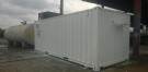

Office Container 20'
Shop info
- 62 Nguyen Cuu Van Street - Ward 17 - Binh Thanh District - Ho Chi Minh City
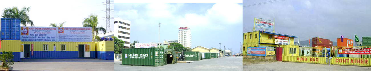
Hung Dao Container
PRODUCT INFORMATION
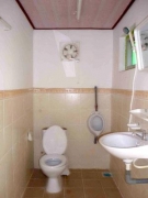
TYPE OF PRODUCT: OFFICE CONTAINER 20FT TOILET
CONTAINER: IICL OR CW STANDARD - GOOD QUALITY
DIMENSION: Length: 6,058 (mm)Width: 2,438 (mm)
Height: 2.591 (mm)
INTERIOR DETAIL - OFFICE CONTAINER 20FT
POWER SYSTEM
Wiring System: installation inside the wall
02 sets of single light 1.2m + switch off
03 dual power sockets
01 exhaust fans + switches
01 CB external source 50A.
01 air conditioners (1.5 HP) + CB air conditioner
FLOOR:
Covered with PVC
WALL & CEILLING CONTAINER
Wooden frame design, MDF panel with foam insulation
WINDOWS & DOORS
Two aluminum sliding glass windows (1 x 0.8m), with cover roof
An steel doors with the top half to the glass (W 0.8 m x H 2m).
PAINT AND EQUIPMENT
Handle container surface and paint a coat of paint outside
* All inside equipment is the new 100%, new air conditioning is warranty 2-year on manufacturer
Maintenance Manual Suggestion Guidelines
.jpg) 2017.8
HDO INTERNATIONAL INCORPORATE
Suggestion Normal Maintenance and repair
2017.8
HDO INTERNATIONAL INCORPORATE
Suggestion Normal Maintenance and repair
CONTENTS
Suggestion Normal Maintenance and repair.................................................................. 1
1. Frame........................................................................................................................... 2
2. Check the Kingpin for Wear:........................................................................................ 3
4. Landing Gear................................................................................................................ 4
5. Suspension................................................................................................................... 6
6. Slider Bogie.................................................................................................................. 7
7. Axle.............................................................................................................................. 8
8. Rim & Tire.................................................................................................................... 10
9. Brake System............................................................................................................... 11
10. ABS System................................................................................................................ 13
11. Air Line Maintenance................................................................................................. 16
12. Electrical System........................................................................................................ 17
|
Time Intervals (Mileage intervals noted below if recommended) |
Initial Period |
Periodic Checks |
|||||
|
Every Month |
Every 3 Months |
Every4 Months |
Every 6 Months |
Every 12 Months |
At brake Reline |
||
|
Frame Structure |
|
|
|
|
|
|
|
|
Fasteners on frame in place |
|
|
|
|
|
|
|
|
Torque and Corrosion of Fasteners on frame |
|
|
|
|
|
|
|
|
Kingpin and Upper Coupler |
|
|
30,000 |
|
|
|
|
|
Locking Device |
|
|
|
|
|
|
|
|
Landing Gear Lubrication (Saf-Holland) |
|
|
|
|
|
|
|
|
Hardware of Landing Gear Inspection |
|
|
|
|
|
|
|
|
Cracking and/or Wear of Suspensions |
|
|
|
|
|
|
|
|
Torque and Corrosion of Fasteners on Suspension |
|
|
|
25,000 |
|
|
|
|
Torque of Fasteners on Pin Cage and Hold-down Brackets of Slider Frame |
1,000 |
|
|
25,000 |
|
|
|
|
Hub Cap and Wheel Seal |
|
1,000 |
|
|
|
|
|
|
Brake Adjustment & Repack Wheel Bearing |
|
|
|
|
15,000 |
|
|
|
Lining wear Checking and estimate replacement time |
|
|
|
|
|
30,000 |
|
|
Camshaft & Components Checking and Lubrication |
|
|
|
|
|
30,000 |
|
|
Brake Drum |
|
|
|
|
|
30,000 |
|
|
All Components of Wheel End |
|
|
|
|
|
|
100,000 |
|
Brake Chamber & Slack Adjuster |
|
|
|
|
|
|
100,000 |
|
Lug Nuts & Hub Cap Nuts |
50-100 |
10,000 |
|
|
|
|
|
|
Brake chamber push rod travel |
|
300 operating hours /8,000 |
|
|
|
|
|
|
Wear or broken checking & Lubrication of Brake Adjuster & Clevises |
|
|
|
|
1,800 operating hours /8,000 |
|
|
|
Air brake System |
|
|
|
|
|
|
|
|
Electrical System |
|
|
|
|
|
|
|
1. Frame
|
Item |
Check for |
Interval |
Note |
|
Visual Inspection |
Missing components Visible obvious cracked welds Visible large cracks in metal Badly distorted components Severe corrosion Large loose of paint Extension frame lock pin’s proper functioning Slider lock pin’s proper functioning Lifting lock’s proper functioning |
Before use
|
Walk round the chassis before every trip to check for obvious damage.
|
|
Periodic Inspection
|
Torques of fasteners Cracked welds Cracks in metal Missing and distorted components Periodic Inspection Corrosion Loose paint Extension lock pin’s & slider lock pin’s & rotatable lock assembly’s proper functioning |
At least every 3 months |
Look up the “parts manual” to find out the names and numbers of the parts which need to be replaced.
|
2. Kingpin and Upper Coupler Plate
Visual Inspection
Inspect the kingpin and the upper coupler plate for visible cracks and distortions, and any other visible defects before use. Replace the components if there is any visible defect.
| Caution |
|
Check to ensure the kingpin is properly matched with the fifth wheel before every trip. |
Overall Inspection
Complete the following procedures to inspect and maintain kingpin and upper coupler plate every 3 months or 30,000 miles, whichever occurs first, to assure proper and safe kingpin/fifth wheel coupling.
1. Check the Kingpin for Dimensions
Check the kingpin on both longitudinal and transverse centerlines. Place the top of the gauge in contact with the upper coupler plate and slide it over the kingpin. If the kingpin does not pass through the kingpin slot with the top of the gauge in contact with the upper coupler plate, the kingpin and/or the upper coupler plate may have distorted excessively and should be replaced or repaired.
2. Check the Kingpin for Wear:

Use a kingpin gage to check the wear. Replace the kingpin if the excessive wear is found.

3. Check the Kingpin for Damage:
Inspect the kingpin for any nicks, gouges, deformation or cracks which may interfere or affect the use of the kingpin. Replace the kingpin if any damage is noted.
3. Locking Device
- Before each trip, ensure that the locking pins and twist locks are in the working condition and properly locked.
- Check weld or metal cracks.

4. Landing Gear
Inspection and Maintenance Interval
|
Item |
Interval |
Notes |
|
Visual Inspection |
Every use |
Replacement/repair required if components visibly damaged, loose, or broken. |
|
Lubrication |
SAF-HOLLAND: Every 6 months *Unless No Lube option selected |
More frequently in excessively moist and dusty conditions, as well as if not used for extended periods of time. |
|
Hardware Inspection |
Every 6 months |
|
Visual Inspection
Inspect the landing gear for cracks, bent components, or damaged/missing hardware, and any noticeable defects before use. The landing gear must be repaired prior to avoid damage and possible injury.
| Warning |
|
Failure to check the condition of landing gear prior to operating could result in use of damaged product which, if not avoided, could result in death or serious injury. |
Lubrication
The landing gear requires lubrication whether it is used frequently or sits idle for extended periods of time. If left idle and un-greased, hard cranking could result. Use high quality grease for normal applications. For low temperature applications, use low temperature grease.
Comply with the following procedure:
- Place the chassis on level ground, chock the tires, and support the chassis without using the landing gear.
- Fully retract the landing gear, then using high gear, extend the leg several turns (specified in the landing gear specification).
- Lubricate through the grease fittings on the gear.
- Distribute the lubrication by fully extending .
Hardware Inspection
Perform the following procedures to ensure the landing gear is in proper working order:
- Tighten or replace the mounting bolts as necessary.
- Inspect the mounting bracket for cracks or other signs of damage.
- Repair or replace any broken or damaged part of the landing gear assembly or mounting structure.
Inspect the crank handle bolt and the lock nut. Tighten or replace as necessary (the crank handle bolt must be loose enough to allow free engagement).
- Inspect the crank handle. If the handle connecting tabs, tube or grip are bent or damaged, replace the handle.
- Cross shaft connection bolts and lock nuts should be secure, but allow side-to-side play in the cross shaft.
- Inspect the footwear for damage and replace if the components are bent or cracked. If removable footwear is present, ensure all mounting bolts and fasteners are tightened and footwear is secure.
- Check for proper shift shaft engagement in both high and low gear and proper shifting between gears. Rebuild if necessary.
- Rebuild or replace the landing gear with excessive play in the shafts and bushings.
| Note |
|
Ensure that the torques of fasteners connecting the shafts meet the torque values shown in the following figure. |
.jpg)
5. Suspension
Suspensions, by design, require a minimum of maintenance. However, suspensions in “over-the-road” operations require periodic checks to maintain continuous trouble-free performance.
| Warning |
|
Broken or misaligned spring leaves, missing or loose U-bolts, or other defective conditions likely to cause axle shift are hazardous. |
- Check the chassis alignment and correct it if needed. The dimensions must be within 1/8”. Check the front-to-rear axle-end dimensions. The
.jpg)
dimensions must be within 1/16”.
- Inspect all decals to ensure they are clearly legible and intact. Clean with a terry cloth towel, soap and water.
- Check all bushings for wear. Replace any worn bushings and re-torque the mounting hardware to the manufacturer’s recommended specifications.
- Check welds to see that no cracking has occurred between the spring seats and axles, and between the hangers and sub-frame. Check for cracks in springs, rockers, and hangers. Note excessive or unexpected wear and corrosion. Check to see if the equalizers are free to operate.
Check all the fasteners in an initial break period, approximately 1000 miles, and at least every 4 months or 25,000 miles periodically thereafter. All bolts and nuts should be checked to insure that recommended torque values are
.jpg)
6. Slider Bogie
Intermodal/ISO Chassis equipped with sliding suspensions can redistribute cargo weight on the chassis axles by moving the suspension under the Intermodal/ISO Chassis. Moving the suspension forward increases the weight on the chassis suspension and moving it to the rear increases the weight on the tractor.
· Check and verify that all the locking pins are fully extended and pass through the locking holes in the frame rails, before moving a chassis.
· Check the pin cage assembly and hold-down brackets at the front and rear of the slider frame are undamaged and secured. Check the bolt torques in an initial brake period, approximately 1000 miles, and at least every 4 months or 25,000 miles periodically thereafter.
· Lubricate the pins and pivots.
· Remove grit and rocks between the pin cage/hold-down bracket and chassis frame. Lubricate the contacting surface if metal-to-metal contacting occurred.
· Check the locking pins, links, rods and springs for wear or distortion. Be sure all links operate and fully extend the pins through the matching holes in the rail.
· Inspect slider wear pads for excessive wearing. Replace as needed.
· Check the sub frame, gussets and welds for cracks, broken parts or welds.
.jpg)
1. Air tank.
2. Supply air line.
3. Solenoid valve 3 port. (kéo khóa ra phía sau rơ mooc sẽ đẩy ty xy lanh ra, khóa chốt hãm)
4. Air line push acting air cylinder
5. Air line pull acting air cylinder
6. Air cylinder7. Axle
It is important to inspect all axle components for damage or wear, and to repair or replace them as required before assembly. Performing these procedures can help preventing future problems.
EVERY 1,000 MILES
• Inspect hub cap and wheel seal area for grease leaks.
15,000 MILES OR MINIMUM OF TWICE A YEAR
• Check brake adjustment.
• Repack wheel bearings.
30,000 MILES OR MINIMUM ONCE A YEAR
• Check lining wear and estimate replacement time. Replace with new shoes or reline when thickness of lining is ¼ inch at thinnest point, or 1/16 inch above rivet or bolt head. Replace any cracked, broken or oil-soaked linings immediately.
• Inspect camshaft, camshaft spider bushing, and camshaft support bracket bushing for any signs of wear.
• Lubricate camshaft bushings.
• Inspect brake drums for heat checks, grooves, hot spots, glazing, cracks, and out of round.
AT EVERY BRAKE RELINE
• Replace wheel bearing lubricant
• Repack wheel bearings
• Check brake air chambers and slack adjusters.
• Inspect brake rollers, roller shafts, anchor pins and bushings and replace if necessary.
• Lubricate brake adjusters.
• Check shoes for bent shoe ribs, cracks in shoe table welds or ribs, and elongated rivet holes.
Replace shoes if any of these conditions exist.
Axle
|
|
PERIODIC CHECKS |
||||
|
WHICHEVER OCCURS FIRST |
MILEAGE INTERVALS |
After First 3,000 Miles |
Every 10,000 Miles |
Every 50,000 Miles |
Every 100,000 Miles |
|
TIME INTERVALS |
After First Month |
Every Month |
Every 6 Months |
Every 12 Months |
|
|
VISUAL INSPECTION for wear / damage |
|||||
|
Check brake linings for wear |
|
|
|
|
|
|
Check S-camshaft for proper |
|
|
|
|
|
|
Check slack adjusters for correct function. |
|
|
|
|
|
|
Check air brake system for leaks (brake applied). |
|
|
|
|
|
|
Check axle structural omponents for cracks or damage. |
|
|
|
|
|
|
Check hub lubrication level or excessive leakage |
|
|
|
|
|
|
MECHANICAL CHECK |
|||||
|
Attention: Torque check wheel nuts after the first 30 miles (50 km) and 100 miles (150 km) (repeat also after every wheel removal). |
|
|
|
|
|
|
Torque check all nuts and bolts to recommended setting. |
|
|
|
|
|
|
Check and adjust wheel bearing end play. |
|
|
|
|
|
|
Pack hub bearings with fresh lubricant (also after every brake lining replacement, check hub bearing wear). |
|
|
|
|
|
|
Lubricate S-camshaft bearing bushings. |
|
|
|
|
|
|
SAFETY INSPECTION |
|||||
|
Check brake lining to drum clearance for correct adjustment – readjust clearance if necessary. check service brake and parking rake forperformance. |
|
|
|
|
|
Check lug nut and re-torqued after first 50 to 100 miles of use and every time you change a wheel or a Lug Nut is disturbed/replaced. Check Rim for Rust Streaks running down wheel from behind Lug Nut from stud indicating Loose Lug Nuts. Check torque of lug nut and hub cap nut as per the torque list below every 10,000 miles, or every month thereafter.
.jpg)
1> Hub cap bolts; 2> Lug nuts;
|
Torque on Axle |
|||
|
Item |
Hub cap bolts |
Size |
Torque (Ft.-lbs.) |
|
1 |
Lug nuts for disc |
5/16-18,GR5 or GR8 |
12-15 |
|
2 |
wheel |
Hub-piloted, M22mm×3.94" Stud |
450-500 |
|
3 |
Lug nuts for spoke |
3/4” BSF |
230-260 |
8. Rim & Tire
Inspect rims and tires for the defects shown in the following table.
|
Item |
Check for |
|
Rim |
Severe rust or corrosion Cracks in metal Bent flanges Rim Rust Streaks behind Lug Nuts Deep rim tool marks on rings or in gutter areas Damaged or missing rim drive plates Loose, missing or damaged nuts or other parts Foreign matter |
|
Tire |
Punctures Bulges Abnormal tire pressure Tire Air leakage Excessive tire abrasions Severe corrosion Foreign matter |
| Danger |
|
Loose nut, cracked wheels, missing nuts or lugs are extremely dangerous and could result in wheel loss, serious injury, property damage or even death |
· Supplement the tire pressure to the value as is listed in the manufacture plate if any tire is under inflation.
· Clean out all the foreign matters.
Tire Rotation
Rotating the tires on the chassis can increase their service life. Rotate the tires on the same axle and different axles regularly. Do not change the rotation direction of any tire in rotation.
Tread Depth
Measure the tires for wear and take the measurement at the same spot on the tread and close to the center groove of the tire in each measurement and calculate the remaining amount of rubber.
Tread Depths should be measured and averaged from check points in 3 separate tread tracks, at 9, 12, and 3, for overall tread depth average of tread remaining.
Replace the tire when the remaining amount of rubber exceeds the limit amount determined by the tire manufacturer.
Inflation Pressure Inspection
Using a reliable tire pressure gauge, inspect tires thoroughly before every use or once a week at least, or whenever under-inflation occurs. Check it when the tire is cool. Inflating to the recommended pressure (but not exceeding the pressure limit molded into the tire and the rim or wheel rating). Always use valve stem caps to keep a tight air seal and keep out dirt and moisture.
Even with proper inflation, radial tires tend to show a sidewall bulge normally associated with under inflation. After mounting a new tire, recheck inflation pressure after 48 hours.
Inflation pressure increases during normal operation as tire temperature increases. Higher pressure may be a sign of overloading, under inflation, excessive speed, improper tire size, or a combination of these factors. Determine the cause of any abnormal air pressure increase and correct it. Inflate the underinflated tire(s) when the following inflation is found in each inspection.
| Caution |
|
Inflate tires only to recommended air pressures, which can be found on the label of the chassis. Under inflation and over inflation are both bad for the tire, which may also be the cause of an accident. The tire must be inflated if the tire pressure is 20% below the maintenance value. |
9. Brake System
Brake Chamber
The Brake Chambers are important in the braking system. While they do not require scheduled servicing, it is good preventative maintenance to make the following routine inspections while they are in the shop for regular servicing of other components or at a minimum of every 50,000 miles
| Danger |
|
Intermodal/ISO Chassis axles are equipped with spring brake chambers. Never attempt to disassemble the spring brake chamber without the vendor’s instructions, as serious personal injury could result from accidental sudden release of the high energy spring. It is extremely dangerous and could cause serious injury or even death, if opened! |
- Inspect the cap for damage and replace as necessary.
- Visually inspect the exterior surfaces of the unit for signs of damage from outside sources, corrosion and/or rust.
- Inspect service brake clamp ring to be sure it is securely in place and damage free. If any damage is seen or suspected, cautiously remove the complete piggyback/spring brake chamber following the brake chamber vendor’s instruction.
- Inspect air lines, hoses and fittings attached to chamber. Replace any damaged or leaking parts.
- Inspect the push-rod to be sure it is working free, not bent, not binding and is square to the chamber bottom within ±3° any direction at any point in the stroke of the chamber. If the pushrod is not square, make corrections by repositioning the chamber on the mounting bracket and/or by shimming the slack adjuster to the right or left on the camshaft as required.
Each brake chamber has an orange strip alert stroke indicator on the push rod. Normally it can’t be seen. If it is visible, the brake adjusters are out of adjustment. To check whether the brake adjuster was mounted incorrect or brake lining was over worn. Check to ensure the mounting stud nuts and jam nuts torque following required value.

1> Brake chamber amounting bolts;
2> Jam nuts of clevis;
|
Torque List of Axle, Wheel & Rims |
|||
|
Item |
Fastener |
Size |
Torque (Ft.-lbs.) |
|
1 |
Brake chamber mounting bolts |
5/8"-11,GR8 |
135-150 |
|
2 |
Jam nuts of clevis |
\ |
40-60 |
Slack Adjuster
Automatic Slack Adjuster (ASA for short) designs vary in the manner in which they are installed and operate, all are designed to automatically maintain a predetermined drum–to-lining clearance or brake chamber stroke. The picture below shows the different kinds of ASA from different manufactures.
.jpg)
| Caution |
|
Self-adjusting brake adjusters do not eliminate or reduce the need for periodic inspection and maintenance of the adjuster components and attaching hardware. Self-adjuster brake adjusters should never be operated as a manual adjuster, if the self-adjusting function is not operating properly. |
Every month, 8,000 miles, or 300 operating hours, check brake chamber push rod travel; chamber stroke should be in compliance with the maximum allowable adjusted strokes as shown in the table, without the brakes dragging or the push rod binding.
|
Chamber Type VS. Maximum Legal Stroke at 90-100 PSI Brake Application Pressure |
|
|
Chamber Type |
Maximum Legal Stroke |
|
3030 |
2.0” or Less |
|
3030 Long Stroke |
2.5” or Less |
Every 6 months, 50,000 miles, or 1,800 operating hours, lubricate all brake adjusters and clevis pins. Check for worn clevises, clevis pins, and worn or broken control arm/attaching brackets. Failure to replace worn, broken, or disconnected components will increase chamber stroke. More stringent lubrication and inspection intervals may be needed according to the service condition of the chassis.
10. ABS System
Intermodal/ISO Chassis equipped with ABS feature an amber warning lamp mounted to the driver’s side of the chassis. The ABS warning lamp should illuminate during initial power application to the primary constant (blue) circuit or backup power (red) circuit, and then extinguish in a few seconds after a successful system self-check.
- If the warning lamp DOES NOT COME ON AT ALL, replace the warning lamp.
- If the ABS warning lamp COMES ON and STAYS ON, even after pulling the chassis forward at greater than 4 mph, then a fault exists (or an intermittent fault has existed) somewhere within the ABS system.
If the ABS Warning light goes ON and remains ON in the trip, the ABS portion of the brake system is not working. The ABS must be serviced as soon as possible upon completion of your trip to ensure full anti-lock braking capability. The light will come on and stay on until the problem is fixed.
| Warning |
| Do not weld on the chassis when the ABS power is on. |
For optimum performance and long life of the chassis’ ABS system, periodically check the ABS system and components:
- Inspect the ECU valve, sensors and air line installation.
- Inspect the sensor cable and air hose for cracks, missing sections, damage or contamination.
- Check ABS functions, perform end of line test and fault code check.
WABCO ABS Blink Code Diagnostics
The Meritor WABCO Enhanced Easy-Stop Chassis ABS ECU detects any electrical fault in the chassis ABS. Each of the faults has a code. When a fault occurs, the ECU stores the code for that fault in the memory. But it only displays one blink code at a time. This is why it is important to recheck the blink codes after repairing a fault. If there are additional codes in the memory, they only blink after you have repaired the first fault.
The ECU signals a malfunction by lighting both the internal and external indicator lamps when a fault exists. To obtain blink codes using ignition power activation, perform the following procedure:
1. Turn the ignition switch on for no longer than 5 seconds. The ABS indicator lamp will be on.
2. Turn the ignition switch off. The ABS indicator lamp will go out.
3. Turn the ignition switch on. The ABS indicator lamp will then come on, then go out.
4. The blink code will be displayed three times by the ABS indicator lamp on the chassis.
|
Meritor WABCO Blink Codes |
||
|
Blink Code |
Problem Area |
Action |
|
3 |
Sensor BU1 |
Determine sensor location. Check sensor installation. Make necessary repairs. |
|
4 |
Sensor YE1 |
|
|
5 |
Sensor BU2 |
|
|
6 |
Sensor YE1 |
|
|
7 |
External ABS modulator valve |
Verify proper electrical installation. Check power supply. Make necessary corrections |
|
9 |
Internal modulator failure, inlet valve #2 |
Verify proper installation. If code continues, contact Meritor WABCO or SEALCO for assistance.
|
|
10 |
Internal modulator failure, inlet valve #1 |
|
|
11 |
Internal modulator failure, outlet valve |
|
|
14 |
Power Supply |
|
|
15 |
ECU Failure |
|
|
16 |
SAE J1708 Failure |
Internal failure, contact Meritor WABCO. |
|
17 |
SAE J2497 (PLC) Failure |
|
|
18 |
Generic I/O Failure |
Verify proper electrical installation. Check power supply. Make necessary corrections. |
| Note |
| For ignition power activation, power is provided by the ignition switch |
Haldex ABS Blink Code Diagnostics
Haldex 2S/1M Simple Mode Blink Code Access
Apply trailer brakes to turn on stop lamps; then turn ignition switch on for 1 second, off for 1 second, then back on. Observe trailer mounted warning lamp.
|
aldex Blink Codes |
||||
|
Item |
Item Simple Mode Flash Count |
Actual Fault |
Explanation |
Solution |
|
System OK |
Lamp stays on ** |
07 |
No fault found ** |
ABS ECU is fully perational. Displays:07. Vehicle stationary. |
|
Sensor 1A |
1 Flash |
01 |
Curbside wheel speed Sensor S1A, or sensor wiring, has an open or short circuit. |
Check cable connections. Check sensor for 980-2350 Ohms resistance. Check for pinched sensor lead which may cause an intermittent short or open. Replace cable or sensor as necessary. |
|
Sensor 1B |
2 Flashes |
02 |
Roadside wheel speed Sensor S1B, or sensor wiring, has an open or short circuit. |
|
|
ABS Valve |
7 Flashes |
61 |
Hold solenoid open circuit on ABS valve. |
Check solenoid cable and connection. Connection should be clean and free from moisture. Apply light dielectric grease to pins. If okay, the solenoid on the ABS valve may be defective. Replace with AQ40525 kit. |
|
67 |
Dump solenoid open circuit on ABS valve. |
|||
|
71 |
Hold solenoid short circuit to ground on ABS valve. |
|||
|
81 |
Hold solenoid short circuit to B+ on ABS valve. |
|||
|
87 |
Dump solenoid output shorted to B+ on Red valve channel. |
|||
|
Low Voltage |
10 Flashes |
90 |
Low supply voltage fault. Does 10 Flashes 90 NOT latch. Is not stored in memory. |
Power supply voltage level at ECU is less than required. Check power supply and ground wiring. DO NOT USE A BATTERY CHARGER AS POWER SUPPLY. |
|
ECU Failure |
11 Flashes |
93 |
Short circuit on ABS ECU internal relay. |
Defective ABS ECU, valve cable or solenoid. Verify solenoid and valve cable. If good, replace ABS ECU only. |
|
90 |
ABS corrupt memory. |
Defective ABS ECU. Replace ABS ECU only. |
||
|
E-Code s |
E0 thru EF are generated when internal problems exist within the ABS ECU. |
Defective ABS ECU. Replace ABS ECU only. |
||
** If Simple Mode does not reveal any fault codes, but the ABS lamp remains “NO” after powering up the
ABS, there may be dynamic faults stored in memory.
Dynamic faults usually occur because of excessive sensor air gap (set to 0.00”) or loose wheel bearings.
After repair, roll vehicle over 6 mph to extinguish warning lamp.
11. Air Line Maintenance
Air Brake Schematic:
.jpg)
Recommended experiences are listed as below to maintain the optimum performance of air PiPes.
Visual Inspection:
- Check the connectors, seals and hoses for cracks, missing sections, damage or contamination. The brake hoses and tubing should not rub against any part of the Intermodal/ISO Chassis.
- Drain the air reservoir of water and contamination daily. This is particularly important in wet, cold weather.
Check the following items every three months. Meanwhile, any of the following conditions requires immediate system shut down and replacement of worn or damaged components:
- Air leakage: Look and listen to see if there are any signs of visual damage to any of the components in the system. Leakage is an indication of worn or damaged components.
- Damaged or degraded components: Look to see if there are any visible signs of wear or component degradation.
- Kinked, crushed, or damaged hoses. Kinked hoses can result in restricted air flow and lead to unpredictable system behavior.
- Any observed improper system or component function: Immediately shut down the system and correct malfunction.
- Excessive dirt build-up: Dirt and clutter can mask potentially hazardous situations.
| Release the air pressure in the system before any component replacement operation. Leak detection solutions should be rinsed off after use. |
12. Electrical System
Comply with FMVSS 108, the chassis will be wired for 12V DC electrical system. Harness system will be STA-DRY design. LED lamps will be flange mounted on the frame by stainless rivets.
Wiring Schematic:
.jpg)
A 7-way receptacle located on the front of your chassis. Each terminal carries current from the tractor electrical source through a circuit to various electrical devices. Individual circuits may be traced by various wire colors. Shown below is the circuit wire color and the electrical device it serves

For optimum performance and long life from the Intermodal/ISO Chassis lamps and wiring, follow this inspection procedure.
Check reflective tape and reflectors on the chassis sides and rear:
There must be a minimum of 50% of the overall chassis length of 2” wide, alternating red and white reflective tape on each side of the chassis. Clean any dirt or grime off tape for maximum visibility.
Pay attention to the position and direction of reflective tapes on rear end, as which are required by laws and regulations.
Check to see all reflectors at front & rear ends are in position and undamaged. Clean any dirt or grime off tape for maximum visibility.
Check wiring and harness along the chassis:
Inspect all wiring to see that it is not damaged, and that it is properly supported and protected, with all connections tight.
Check all lights for position and illumination. If any light is not working:
- Check for power at 7-way plug.
- Inspect main harness at 7-way plug.
- Check for power at rear sill harness. First check tail light for power. If no power, check where rear sill harness plugs into main harness.
- Check for corrosion. Corrosion may occur on wires, connections, lights (bulbs), and light and harness prongs.
- Check for unplugged wires. Make sure connections are completely sealed.
- Check for burned out light (both filaments).
- Clean and/or replace any dim lights.
| Note |
| Most Intermodal/ISO Chassis are equipped with a sealed wiring harness. Check the circuits at the plugs only – do not cut or probe test for shorts. Every time the harness is unplugged, repack connector with Grafo 112X grease or equivalent. |
|
CONTAINER PRODUCTION LINE |
|
THE FIRST STEPS ... (2004)
With two production lines CONTAINER fully equipped with machinery and systems testing the international standard model, Hung Dao Container has entered into high quality ISO container production market for domestic market and export. Although our annual output is only a small part of global container production. But that is a contribution to the first steps of Vietnam as a nation with containerized production in the world. JUST THE FIRST STEP TO CONTRIBUTE TO CONTAINER PRODUCTION IN VIETNAM CIRCULATED WORLDWIDE AFTER THE FIRST STEPS ... (2009) Over the years produced container, Be more confident of customer in domestic and overseas, With higher output and quality, Containers produced in Vietnam have integrated into the world, CONTAINER VIETNAM HAS INTEGRATED WITH THE WORLD |
Issue: July 2004 | WorldCargoNews
Boxes from Vietnam
It may be a drop in the bucket when compared to the Chinese container manufacturing giants, but Vietnam has taken its first steps on the road to becoming a box building nation. Best known as a depot operator, Hung Dao Container Co started building standard steel dry freight boxes at the beginning of June at a factory at HoChiMinh City. Capable of building 20 ft, 40 ft and 40 ft high cube boxes, the facility is currently producing 20 TEU/day, around half its installed production capacity of 6000 TEU/year. All raw materials are imported from Japan, Korea, China and Malaysia. Initial deliveries are reported to have been made to customers in Europe, the US, Autralia and Dubai. (excerpts form World CargoNews) |
.jpg) |
.jpg) |
.jpg) |
.jpg) |
.jpg) |
.gif)
Company images